Maker Faire 2024: The Invisible World of Radio Waves
Welcome to the project page for Maker Faire Lake County 2024. We have been working very hard to prepare for the Faire. The Faire was well attended and we enjoyed talking with you and hope you enjoyed your visit at our exhibit. After the Faire, we will be updating this page with more information about the projects from the Faire and addressing your questions in greater depth.
“Get RadioActive” Badges
As Makers, it is all about learning and making. For this year’s Faire, we wanted to remind visitors about our exhibit by creating a keepsake. This is how the idea of the “Get RadioActive” badge came about. Besides creating a colorful “blinky” badge that reminded visitors where to go for more information about amateur radio, it provided an opportunity for us to learn new techniques and to solve some interesting challenges.
![]()
The process began with designing the front of the badge. The size of the badge was chosen to be similar in size to the popular “Hello., I’m..” stickers or membership badges for clubs and organizations. The message would have to be kept simple, provide a way to contact MCWA (McHenry County Wireless Association) for more information, and have a catchy graphic. Originally, the use of a QR code for contact information was considered, but it was decided that there wasn’t enough room to accurately 3D print it without sacrificing the core message or graphic. The photo above shows the final design, which includes a colorful “antenna” graphic with a multi-color LED in the center to depict radio waves being sent out. The badge is a three color design: yellow, black, and red. More on how that was accomplished with the Prusa i3 MKS3+ printer will come later.
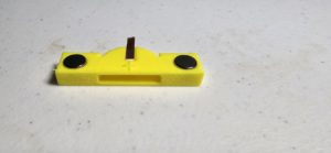
The second component was the back of the badge that held a single 3 volt CR2032 battery to power the LED as well as two mounting magnets. The magnets allow the badge to be attached to a metal surface such as a refrigerator or to clothing using a magnet badge clip, which was also designed. Several iterations of the back were built and tested. It was planned to have some type of on/off mechanism to conserve the battery, but ultimately a design that allowed the battery to be slid out from the holder was chosen for cost and assembly time. Another challenge was how to connect the battery to the LED. Paper clips, solid wire, and DuPont connectors (the type of connector pins used when breadboarding projects) were prototyped. The DuPont connector pins gave the most consistent results, but required gluing two of the connectors to each battery holder and then soldering the other end of the wire to the LED. This approach was ruled out due the added effort to glue the connectors to the PLA badges and time it took to strip, tin, and solder two wires to 50 LEDs. The approach that was chosen was to use 3 millimeter wide, 32 gauge flat copper wire used for jewelry craft making (available on Amazon or a craft shop). This turned out to be nearly a perfect choice. The flat wire formed and hugged the top and bottom of the battery compartment and was easy to directly solder the leads from the LED to the wire. It dramatically cut down on the assembly time of the badges, which was important considering the number of badges to construct.
The battery holder was designed using OpenScad as Ralph is a computer programmer and OpenScad felt a more natural choice for him. You could translate that as “I could have used Fusion 360 or even TinkerCad, but time was running out to learn another tool.”
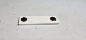
The next challenge was to attach the 8 mm diameter by 3mm high magnets to the back of the battery holder. The first approach was to size the holes such that the magnets could be press fitted into the holder and have a tiny part of the magnetic above the battery holder. A hole diameter of 8.1 mm and 2.5 mm deep was chosen. Initially, that seemed like a viable solution, but two problems were encountered. The first challenge was inserting the magnets firmly into the hole insuring that both magnetic poles faced the same direction. This would become very important when the matching magnetic back clips were made. This problem would remain regardless of the way the magnets were attached to the battery holder. The bigger problem was slight variances in either the hole size or the diameter of the magnets were just great enough to cause one or both of the magnets on some badges to detach after repeated use. It was clear that it would be necessary to glue the magnets to the holder and magnet badge clip.
There are a number of household adhesives that bond well to the metal magnets and the PLA plastic badge material. The goal was to find the right combination of ease-of-use and working time. First up was CA glue (SuperGlue). It is easy to use and the right glue could be purchased that allowed a reasonable bonding time. The first tests looked promising, but adhesion to some badges was poor, probably due to the porous nature of the filament. Too many of the first run of badges had to be reworked to fix magnetics that wouldn’t adhere properly.
Next up was a two-part epoxy. That DEFINATELY would do the trick. However, the setup and working time required careful attention when gluing up dozens of badges and magnetic clips. It was a time consuming process requiring mixing up small batches of epoxy and gluing a few badges at a time. It was also a smelly process which required adequate ventilation.
The third attempt was to use E6000 adhesive popular for crafting and other uses. This glue dries clear, is somewhat flexible (not particularly important for the use here, but a nice characteristic for some projects) and sets within a few minutes with a 24-hour full cure time. This adhesive was used in other 3D printed projects with great results. The adhesive also requires adequate ventilation so a fume extractor was used in addition to working in a well ventilated area. E6000 comes in a number of different sizes and packaging. The remainder of a 3.7 oz tube was used to glue the battery holders to the back of the badges, while a 2 oz tube with precision tips was used to deposit just the right amount of glue into the holes for the magnets. Both tubes are available from Amazon or a big-box hardware store such as Menard’s or Home Depot. Two tips when using E6000: 1) Keep the cap tightly on the tube when not in use. The glue will begin to thicken when exposed to air. I usually squeeze the tube gently and wipe away a bit of the glue with a paper towel before use and 2) wear Nitrile or other type of protective gloves. Beside protecting your hands from the chemicals in the glue under normal use, these tubes are prone to split open if too much force is applied and the glue will get all over you and perhaps your project. How do I know this? Don’t ask. Slow and easy is the way to go.
As mentioned earlier, it is important to have the magnets placed so that the poles of both magnets on the battery holder point to the same direction. It doesn’t matter at this point if the North or South pole faces upward, only that both magnets point in the same direction. The easiest way to insert the magnets was to place a small amount of E6000 glue in each of the two holes, and taking a stack of magnets, insert them into the holes making sure not to switch the position of the stack of magnets. You should also slide your thumb or finger of the other hand over the newly inserted magnet and then move the stack of magnetics away from the badge to discourage the newly inserted magnet from jumping back home on the stack. After inserting both magnets, the battery holder was placed on a flat surface to cure overnight with enough spacing between them to make sure that the battery holders didn’t get attracted to nearby ones.
The magnetic clips were assembled in the same manner, BUT with the poles reversed (opposites attract, likes repel). After applying the glue to the magnetic strip, the stack of magnets was brought close to one of the battery holders so the magnets were attracted to each other. Then, moving the stack away from the battery holder, the stack was reversed in my hand so they were repelled by the battery holder. With the polarity confirmed, it was possible to start inserting magnets in the magnet clip knowing that the will be attracted to the badge back.
After curing for about twelve hours, more E6000 was used to attached the battery holder to the back of the badge with the flat wires pointing to the top of badge so the LED can be soldered later. Two daps of E6000 were placed on the holder and then pressed to the back of the badge. Once again, the glued badge assembly was left to cure for at least twelve hours before soldering the LEDs to the wires.
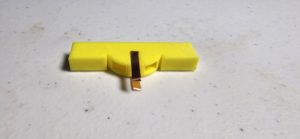
Here is a photo of the glued assembly with the LED press fitted into the badge and soldered into the holder. The positive battery terminal is marked with a “+” sign on the holder. The LED has two leads with the positive lead being slightly longer than the negative lead. If you reverse them, no harm will come to the LED or battery, but the LED won’t light up.
![]()
You may be well aware that it is important to have a current limiting resistor between the LED and battery in order to protect the LED from damage. The multi-color LED used in the project has a rating of 20 ma. The CR2032 has an interesting characteristic in that it has an internal resistance of approximately 200 ohms, which allows the LED to be directly connected to the battery without exceeding the LED rating. This was very helpful for the project since it made soldering the LED to the wires much quicker than it would have been if a resistor would have to be added to the circuit. We did experiment by adding a 100 ohm or 180 ohm resistor and it reduced the current flowing through the LED with only a little impact on LED brightness. This will greatly extend the life of the battery, so if you are making one or two of your own badges, adding a resistor may be a worthwhile consideration.
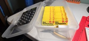
The first set of completed badges:
Bonus: How to you print multi-color 3D prints if your printer doesn’t have multiple extruders or a special filament swapper?
The Prusa i3 MKS3+ printer used to produce these badges only has a single extruder and no MMU. This means only a single color can be printed under most circumstances. It is possible to print multiple colors with a single extruder, but most solutions limit a single color for each layer, somewhat like rings of a tree. Sometimes this is okay (like the front panel markings of the shortwave receiver case, where a the text rising about the panel was fine), but the goal was to have all three colors to be flat and on the same layer.
The technique that was used here was to print the yellow base of the badge and for the last two layers, add in the other colors. Three STL files were created (one for the yellow base, one for the black text, and a third for the red graphic). In OpenScad, the text and graphic files were subtracted from the yellow base layer to make room on the base for the added files. The final piece was using a special printer profile that created five virtual extruders that was created by Rainer S (the technique and link to the profile can be found here: Multicolor printing without a MMU. Using Rainer’s profile isn’t necessary to create virtual extruders, but made the whole process seamless for the Prusa.
The tradeoff is that filament changes have to be done manually, which can make the process a little tedious when using many colors and producing a lot of badges. Producing eight badges at a time took just under five hours with the color changing starting at about two hours and thirty minutes into the print. Pay attention to what color filament to insert next when it is time for a color change. One would think it would be a progression (yellow, red, black, yellow, red, black), but the slicer optimizes the changes so there are fewer changes required. The sequence for these badges, which were applied over the final three layers was yellow, red, black, yellow, red, yellow, black, yellow, and red. Always a good idea to test with a single copy of the model first to avoid disappointment.
Shortwave Receiver Kit
The 40-meter shortwave receiver project that was introduced at last year’s Maker Faire has been updated for better performance and stability. The updated assembly instructions follow.
Download version 1.1 assembly instructions
Download 3D printed case files